FAR BEYOND THE FUTURE


BIM is the process of creating and managing a digital model that represents physical and functional properties of a building, and which is created with help of information technologies in construction industry. This process enables the disciplines, contributing to the design construction and sustainability of a building, such as architectural, structural, mechanical, electrical, infrastructure, fire safety, area arrangement and landscaping to share information in three-dimensional environment.
BIM as an Interdisciplinary Three Dimensional Information Sharing Process:

In BIM process, a structure is modeled in three dimensions by processing all necessary information of all design disciplines. Elements, layers and informations loaded in BIM may be created in different modeling programs for all disciplines. However, all modeling programs being used must support BIM. In other words, the possibility of exchanging data between these programs should be provided, and these programs are combined into a frame program. Thus, the necessary cooperation between disciplines in the BIM design, implementation and management processes are ensured.
All design disciplines are developed in BIM compatible programs that support 3D modeling, and models themselves are combined in the frame BIM program where the main model is digitally built. Thanks to this digital (virtual) modeling, many problems that may affect construction of buildings in real (specific) environment can identified and corrected at the design stage. This does not only contribute to speeding up actual building process, but also helps eliminating additional expenses arising from revisions of the design from the beginning.
By comparing different disciplines of a design in two-dimentional drawings harmonization of only one dimension can be achieved. It is not possible to check vertical (elevation) plans using drawings made in horizontal plans. In other words, plan drawings for all design disciplines, which have been produced for decades, must be supported by cross-sectional drawings. Such a situation with high probability subject to both significant time losses and errors. On the other hand, by integrating designs produced with BIM compatible programs into the frame BIM program, all inputs from all disciplines become controllable in X, Y and Z axes and in every plane. Therefore, efficiency in terms of time and accuracy in the field environment is increased, and delays and cost losses are minimized.
It is necessary to identify the level of standardization in BIM modeling. This level of standardization defines contribution of each designer into the frame BIM model and the level of design details to be assigned. By identifying the standardization level, one can determine which details the end user can see and which data can be accessed in the result model.
Advantages of the BIM Design
• It enables visualization of errors that can occur in upcoming stages of the designing process. Design conflicts, mismatches and errors are detected in digital (virtual) environment during the design stage before the construction stage is started. Therefore, problematic points are revised without additional costs and time losses and long before the construction stage.

• It simplifies decision-making process for the future.
• It stores project data for future use.
• It contributes to the overall project progress within all disciplines. It increases accuracy and makes coordination and exchange of information between different disciplines easier.
• Digital modelling and visualization of the outcome for each design stage increase motivation and efficiency of the both the design team participants and the customer/final user.
• Using climatic and positional data of the project area reflects the relationship of the structure with the environmental conditions.

• Calculation of the quantity of designed elements is easier and errors are much more avoidable. Total cost of construction is also obtained by adding the cost information of the data processed during the design process to the model. In the event revisions are made at any stage, the cost is automatically updated as the input scheme is ready.
• Implementation scheduling and post-implementation maintenance and repair scheduling are provided by BIM supported programs. Therefore, it contributes to sustainability of the project.
BIM Standardization Levels, Contents and Expectations - BIM Dimensions
BIM dimensions allow us to understand which data is added to the modeling. When BIM dimensions are identified for the final BIM model that is generated in the frame BIM program, information about design objects of all disciplines about production timing, costs, sustainability, required maintenance and other aspects becomes available. Although general definitioan of BIM Dimensions are not accepted globally yet, common assumptions are listed in the table below.
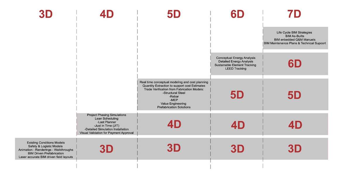
3D-BIM: 3D BIM visualization methods allow participants to see the structure in 3D before the construction phase begins and update the revisions of the structure in 3D throughout the design process. It allows collaboration of participants in analyzing positional and structural problems.
4D-BIM: Unlike 3D, “scheduling data" is entered into a 4D BIM model as a new layer of information. Time information is linked to the elements with help of relevant programs. Therefore, the image of the site is obtained for a desired time frame. This dimension also provides interdisciplinary planning by seeing which elements have been completed, which ones will be started or which will be continued in the project area during certain period of time. The fact that the scheduling made in the 4D model reflects reality is directly related to the correct prediction of work flow and ranking in all branches.
5D-BIM: Provides cost estimations based on 5D-BIM model data. These estimates can be listed as the initial investment cost of purchasing and installing a component, operating costs that may arise during use, and expected price of future replacement based on data for this component.
6D-BIM: 6D-BIM helps to analyze energy consumption. Use of 6D-BIM technology ensures accurate and complete estimates of energy consumption at the design stage. Integrating BIM with 6D-CAD simulation models allows managing consumption of energy with future changes and results in overall reduction in energy consumption.
7D-BIM: 7D BIM is different from 6D by added facility management data. It provides data for parts, namely for their installation, required maintenance and maintenance schedule, their optimal use targeted at increasing performance or saving energy, and their expected life period. With help of this data about maintenance, life period and targeted energy performance, operators can determine costs of these activities and schedule maintenance activities in advance to generate expenditure profiles over the life of the structure.
Another Definition of Standardization in BIM Modeling: BIM Levels
Basically, BIM levels are divided into levels ranging from 0 to 3, where different milestones are defined to bring the construction industry into a full-fledged collaborative environment. These levels are conceptually defined as follows:
BIM Level 0: In its simplest form, level 0 means absence of effective cooperation. Designs made in 2D-CAD environment are used only for transferring information about manufacturing to the site. Output and distribution are performed on paper or electronic prints or combination of both. Current performance of many areas in construction industry exceeds this level.
BIM Level 1: This level usually includes a combination of 3D CAD for core design and a combination of 2D for preparation of the detailed design. Data is usually shared electronically in a common data environment managed by the contractor. Many disciplines currently operate at this level. Collaboration between disciplines is limited; each discipline manages and publishes its own 3D information or 2D drawings derived from these models.
BIM Level 2: The most important aspect of this level is the way of sharing information among the participants. At Level 2, there is no need to share information on a single model. Instead, there may be different parties using various 3D models and design information; they are later converted and shared into a common file format, such as IFC. Standardized format is used to allow parties to combine data or models and manage the design more accurately to reduce the risk of errors and wastes. As a result, BIM Level 2 is about sharing the design information through a standard electronic transfer and combining it into one framework BIM program for managing all information.
BIM Level 3: A single, jointly designed model, maintained in a central repository and produced in the frame BIM program, represents full collaboration between all disciplines. All parties have access to the same model, and they are able to update the BIM model by embedding the models they prepare with 3D programs in their own disciplines into this general model. This eliminates conflicting information and ensures efficiency from beginning to the end.
Detalization Levels in BIM Modeling: BIM LODS
The level of detalization for a building information model increases as the project progresses, based on available initial information. It evolves from a simple design model to a detailed virtual construction model, then to an as-built information model. Different aspects of the model may be developed at different rates.
The BIM-LOD is a generally accepted form of classification that defines the details that building model will contain at different levels. The BIM model has LOD options ranging from 100 to 500.

LOD 100: The building 3D model is developed to represent basic information. At this stage, only a conceptual model (Cubic Model) can be generated. Parameters such as area, height, volume, position and direction are defined on this level.
LOD 200: is a general model where the elements are modeled with approximate size, dimensions, shape, position and direction. Non-geometric information can also be added to the model elements.
LOD 300: Accurate modeling and drawings where elements are defined by specific assemblies, precise quantity, size, shape, position and orientation. Here, non-geometric information also can be added to the model elements.
LOD 350: Includes model details and elements that show how building elements connect with various systems and other building elements. These models typically include details of construction drawings. These details represent actual aplication models. They clarify the design and construction process.
LOD 400: In addition to model elements, their precise quantity, size, shape, position and orientation, higher manufacturing models with complete information on manufacturing, assembly and detailing are produced.
LOD 500: In addition to the parameters of previous levels, installation and maintenance information for the elements is entered. It also provides foreseeing the life cycle of the structure. In addition to actual and specified size, shape, position, quantity, and orientation, non-geometric information is added to modeled elements.
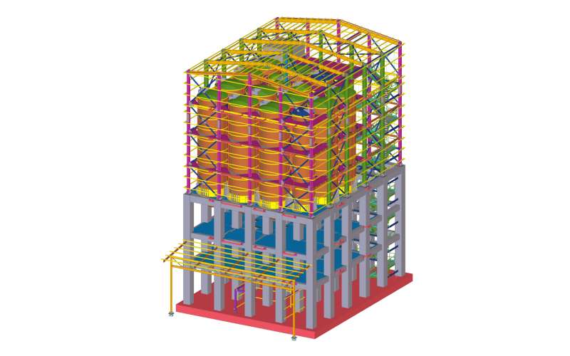
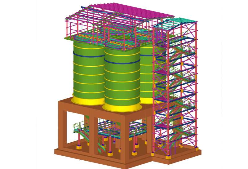
Our BIM Services
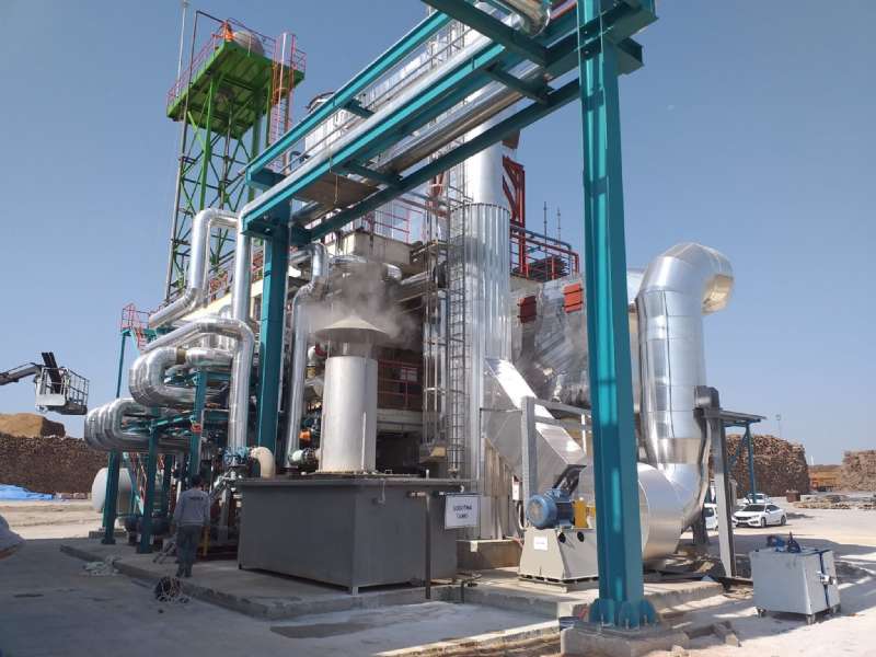
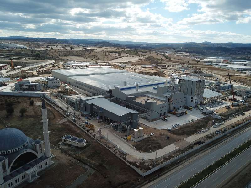
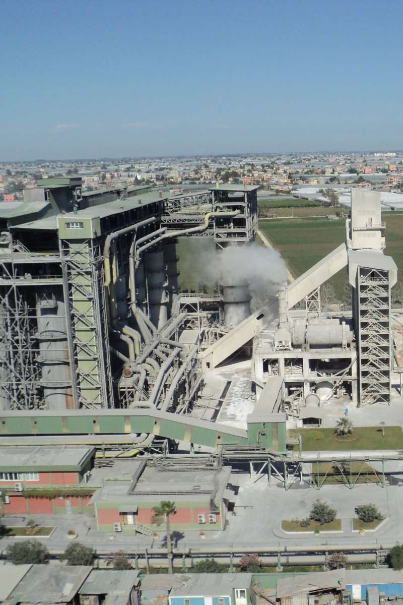
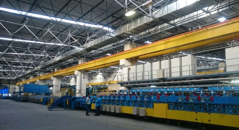
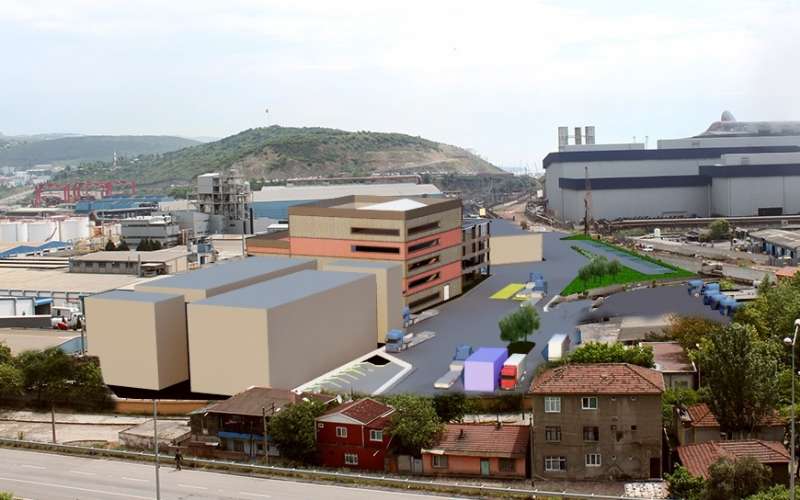
OTS Eng & Consuntancy company develops projects with help of BIM system by making use of technological developments of construction industry. This way, we use advantages of BIM system throughout the process and upon its completion, especially for industrial buildings.
ARCHITECTURAL
For architectural design, we work using the BIM sub-base. By using BIM, along with structure materials we obtain structure's internal and external appearance, the circulation scheme, placement of the building according to land elevations in complex projects, areas that will require excavation and back filling, roads, traffic circulation, approaches to buildings of the complex, as well as dimensions of the building in digital environment before beginning of construction.
We provide our services in the area of architectural design at up to LOD 350 level.
STRUCTURAL
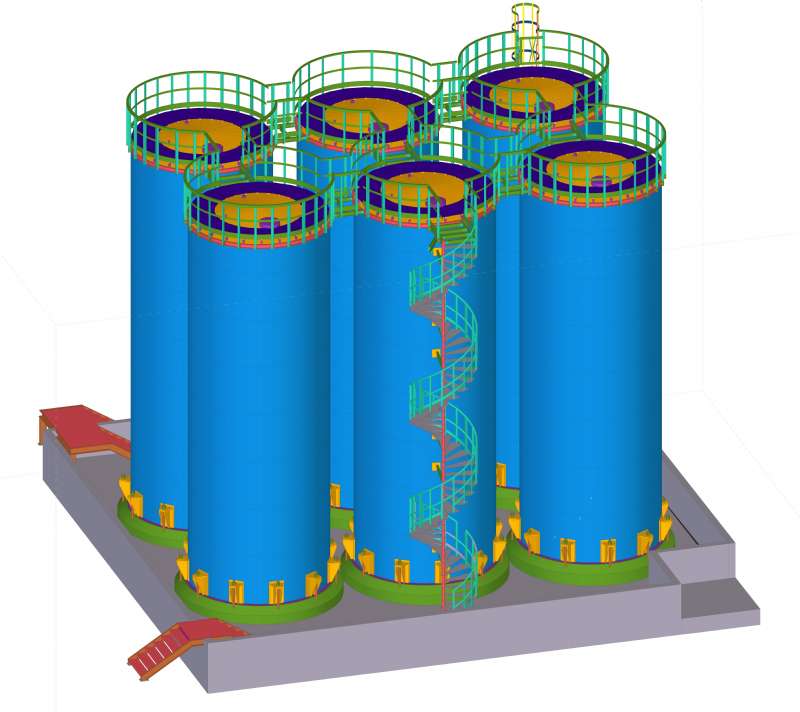
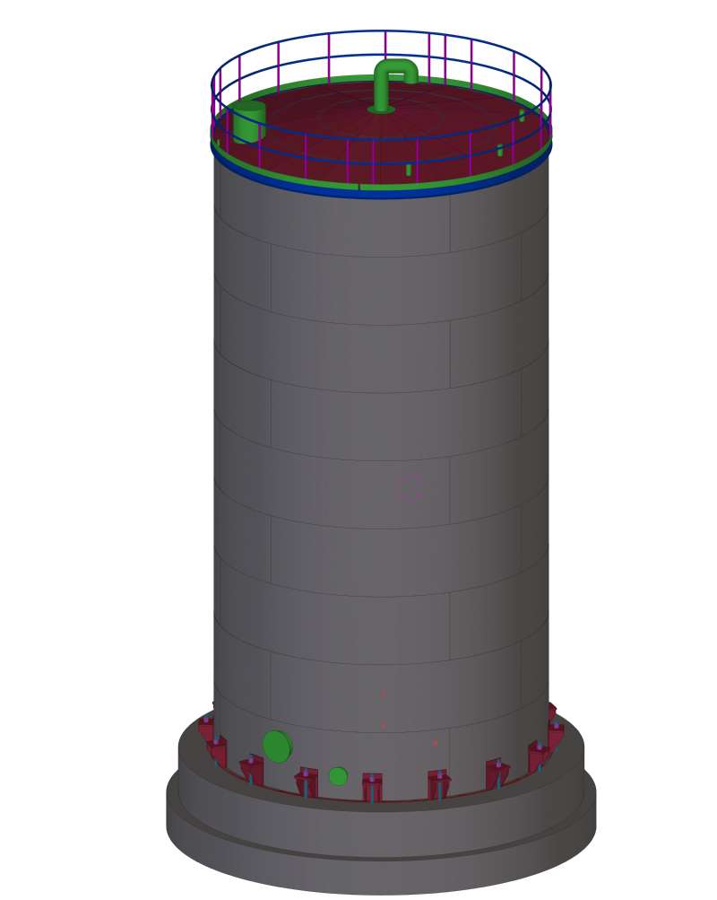
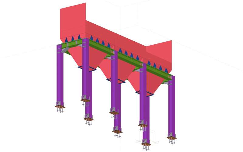
In the area of structural design, we work using BIM sub-base, which allows visualizing intersection of load bearing elements and compatibility of joint points with architectural part before construction, which also helps to ensure efficiency in operation and reduction of errors. In our reinforced concrete, steel, composite, wood and prefabricated load bearing system designs we provide our services in BIM compatible programs
We provide our services in the area of structural design at up to LOD 350 level.

MECHANICAL - ELECTRICAL - FIRE SAFETY
BIM-compliant work on mechanical, electrical and fire safety design provides additional advantages, specifically, the correct layout of the equipment. For instance, we can foresee suitability of shaft locations, the level at which mechanical system can meet the structural requirements, thus reducing error rate in managing collisions/conflicts.

BIM - VIRTUAL REALITY
Virtual reality provides interaction of people with existing or non-existing three-dimensional environments generated by computer technologies. First, an artificial environment is generated. A person, with help of a helmet or goggles, can navigate in the virtual environment at the design stage. The goal is for the user to feel the reality of artificial world, feeling that the real world has been “turned off”.
We provide this service with help of other programs, compatible with the 3D modeling programs we use, which allow us to make virtual reality trips. Therefore, a user, given a feeling of being in a full-scale dimension, is able to experience dimensional and design suitability of the space before construction. In addition, should there be any interdisciplinary conflicts, passages between technical equipment, layout, floor and wall space gaps may be checked as if they were at true eye level.